back

Where we are up to with the development of the club racer in 2014.
![]()
Update 19/12/14During the course of testing and developing parts for the race bike motor things happen which you would rather didn't, one such occurrence is the use of the Mikes XS performance camshaft last year by Ivan in his race motor to verify its usefulness for racing. It was decided that we should try it in Ivan's motor to see if it performed well enough as it was listed as a cam with only street level performance. Ivan duly fitted it to his motor and discovered the boss on the cam used to rephase it rubbed on the bottom of the rocker cover oil feed casting.
It was later found that this bent the camshaft and efforts to straighten it resulted in a crack. This cam is now unusable for our purposes so a replacement has to be found. The cam I favour for our race motor is the Megacycle 250-30 grind.
The specs on the Mikes XS cam is identical to the 250-00 grind. Matt Moloney made us a blank billet camshaft a while ago which I will try to get as he told me it had been put in storage when he moved to Moranbah in QLD. If we can get that, then a copy of the cam we want to use can be made. Matt's blank cam he made for his sidecar cross bike. Also I spoke to Nick McGinn who is going to donate one of his adjustable cam sprockets for the club racer motor. Nick will soon rejoin the club after a few years away, so thanks very much Nick.
|
||||||||||||||||||||||||||||||||||||||||||||||||||||||||||||||||||||||||||||||||||||||||||||||||||||||||||||||||||||||||||||||||||||||||||||||||
Update 16/12/14Ivan Hoey called today to tell me he posted the modified primary drive gear with new needle bearing conversion and adapted clutch basket with heavy duty cushion drive springs ready to be installed in our race motor. This should arrive at Daryl's shop by Christmas. Daryl has set aside the Christmas, New Year break to assemble the motor if all the parts are there ready.
|
||||||||||||||||||||||||||||||||||||||||||||||||||||||||||||||||||||||||||||||||||||||||||||||||||||||||||||||||||||||||||||||||||||||||||||||||
Update 23/11/2014As promised the club racer engine parts were picked up today by Daryl Hutcheon and John Chambers from Terry Gliddon. Here it is loaded up and ready to go in John's van. - 23/11/14
|
||||||||||||||||||||||||||||||||||||||||||||||||||||||||||||||||||||||||||||||||||||||||||||||||||||||||||||||||||||||||||||||||||||||||||||||||
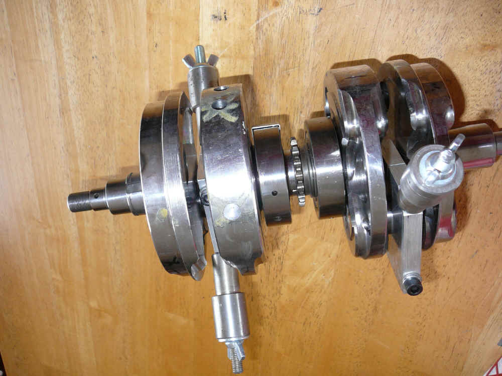
Update 4/10/2014We finally have the crankshaft back from being dynamically balanced and in the picture you can see where it has been drilled. 
Obviously we needed to remove some more weight from the inside flywheel as this measured slightly thicker than its equivalent flywheel on the opposite side of the crank.
With this done the crankshaft spins vibration free on the dynamic balancing machine. 23/10/2014 Because this crank has been heavily modified there has been some bewildering results when spun in the balancing machine. Let me explain this, when we spin the crank in one direction heavy points are identified and marked on each end of the crank. To check this we turn the crank around on the machine and spin it again, this effectively spins it in the opposite direction and the heavy points are identified again but are now in a different position. This was not expected as it was assumed it would identify the same positions. We now think that only spinning the crank in the direction it will spin in the motor and identifying the heavy spots and adjusting the balance in this direction only will get the correct result. Unfortunately time is running out and Johnny is all booked up until Christmas with other work so this will have to be the last attempt to get it right for now. The good news it is very close and the readings being taken now are in the multiply by one scale. 2/10/2014 I went to Melbourne yesterday and picked up the race crank which has now had the centre section fully assembled and loctited ready for balancing. Next job is to get it balanced and then fully assemble with the con rods, align and weld the crank read for use in the race motor. Thanks to Daryl Hutcheon for the work he has done and for the work he has agreed to do by assembling our crank and race motor when the time comes. I will now take it back to Johnny Dyno's for the third time to get it balanced. - Terry Gliddon #275
Update 26/8/14 Last week I collected the crankshaft from Johnny Dyno's and dropped it off at Daryl Hutcheon's so he could assemble the centre section of the crank properly as there was some run out in this section previously which was causing a problem when dynamically balancing. With this centre section assembled with no run out it should be able to be balanced finally. This will be assembled with the rephase shaft and crank sprocket and inner bearings and loctited as per final assembly. Update 17/7/14 Went to Geelong today and dropped the crankshaft into Johnny Dyno's for dynamic balancing, he's going to try and do it for us on Saturday 19/7/14. Today I received some spacers and inlet manifolds from Rob McKie, he has kindly donated these for our club racer's DelOrto carburettors.
3/6/2014 Update Here are the assembled crank halves using the undersized pins with one assembly ready to go on the dynamic balancing machine with the 516 gram weight attached. The drive coupling adapter is also pictured bottom left. After attempting to dynamically balance the crank it was discovered we may have made a fundamental error when statically balancing the crankshaft halves because when they were spun there was an imbalance causing them to jump in the dynamic balancing machine, this was caused by a rocking couple as the inside flywheels had more mass than the outside flywheels. We had mistakenly matched a heavy and a light flywheel together and drilled the same sized hole in each to achieve static balance.
In hind sight what we should have done is paired the two outer lighter flywheels (the two with the starter gear removed) together for static balancing. This would mean these flywheels being lighter would require less material to be removed or a smaller hole to drilled opposite the big end pin to achieve balance with the 516 gram weight attached. If we then matched the two heavier inside flywheels together for static balancing they would require a larger hole to be drilled in them to achieve proper balance with the 516 gram weight attached to the big end pin. If you think about it you will come to the same conclusion we did, i.e. each individual flywheel is now statically balanced to a 50% balance factor so we can now pair them with any other flywheel and still have static balance and because the previously heavier flywheel will now have a larger hole and the lighter flywheels will have a smaller hole they have the same counterweight mass which will not create a rocking couple. To correct our mistake we will now re-balance the flywheels and adjust the hole sizes appropriately, this easy for the heavier flywheels as it means simply drilling a bigger hole but for the lighter flywheels it will mean filling the holes and re-drilling a smaller hole. At least it can be salvaged and we have learned a valuable lesson. We will also be dynamically balancing the crank in one piece and not in two halves as we originally thought.
The two balancing jigs are now made and weigh exactly the same weight of 516 grams as determined in our balance factor calculations. With a little more work we hope to have the crank rebalanced very soon.
As you can see in the picture above the outside flywheels have had the hole size reduced by inserting and welding in some sleeves into the previously drilled hole and the inside flywheels have had the holes enlarged to 25 mm from their previous 20.5 mm. This has now put us in the ballpark for dynamically balancing this crankshaft. I will attempt to get it to Johnny Dyno this week for dynamic balancing. This work has been done by Kevin Palmer and I thank him for his time and effort. What we have done is to add some 11 grams to the outside flywheels and removed about 40 grams from the inside flywheels and by doing this it should dramatically reduce the rocking couple effect we experienced before. Here's hoping we get it right this time, fingers crossed. 22/3/14 Update The very last job prior to Dynamically balancing the crank has now been done, Kevin has made some bright steel temporary big end pins which are slightly smaller than stock which makes them easier to fit but firm enough to stay put when spun in the machine. They are only slightly different in weight (.3 grams heavier) which won't matter in the grand scheme of things. Stock and temp pins are virtually the same weight. Update 20/2/2014 It has been a few weeks since I picked up the water jet cut flywheels and I decided to go with 19mm holes for fear of taking too much weight out of the flywheels. It now transpires that we need to take another 30 grams out of each flywheel after I checked the balance weight after modification.
After drilling a 20.5mm hole in the unusable flywheel is was determined that a hole of this size removed too much weight, actually removed 76grams from the test flywheel so I decreased the diameter to 19mm for the remaining flywheels. This then removed approx. 38 grams from each flywheel leaving a further 30 grams approx. to be removed from each flywheel. The newer flywheels were machined slightly differently hence the different weight distribution and the need to remove more weight than first thought.
Now that the static balancing is done I will make some bob weights for the other jig to clamp the required 516 grams to the big end pin and spin the crank pairs in a dynamic balancing machine which once done will ensure our motor will be perfectly balanced and ready for assembly. The jig as it is now weighs 261.5 grams so the bob weights will have to be approx. 128 grams each. Kevin has also made the spigot which is used to connect the drive cable of the balancing machine to our crankshaft halves. With new bob weights made and attached to the jig it all weighs 515.2 grams which is bloody close to 516grams and perfection. Notice some extra washers for adjustment. As you can see this pair of flywheels are still slightly counterweight heavy with the clamp jig attached with the appropriate weights and clamped to the big end pin. Only job left to do now is to get the drive spigot Kevin made turned down to the size suitable for it to fit into the drive cable on the balancing machine.
Update 9/1/14 Picked up the drilled flywheel I dropped off before Christmas and checked the weight after cutting a 20.5mm hole and it came to 1675grams. Before drilling it weighed 1751 grams. So the 20.5mm hole removed 76grams but ideally we only want to remove 68 grams so when we come to doing the other four flywheels we are going to use in the race motor I will adjust the hole size from 20.5mm to 20mm which should give us the correct amount for removal. Remember this one is the cracked and unusable flywheel and the hole was bored in this one as a trial. It will cost $60 to get the other 4 flywheels done. Once this has been done we can get the dynamic balancing done and then assemble the crankshaft.
|
||||||||||||||||||||||||||||||||||||||||||||||||||||||||||||||||||||||||||||||||||||||||||||||||||||||||||||||||||||||||||||||||||||||||||||||||
![]()