
![]()
|
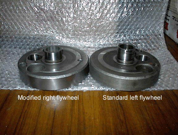
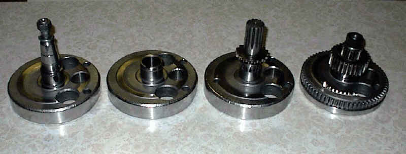
Bob Bertaut in the US has come up with
an ingenious way of rephasing the XS650
crankshaft to 90°. His idea is to use
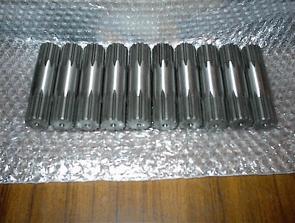
two internally splined flywheels
(number2) at either end of a custom made
splined shaft as shown in the pictures
below. The new splined shaft and the
modified number two flywheel now
replacing the discarded number three
flywheel.
The splined shafts have the splines slightly offset allowing the 90° rephase not possible with the standard crank and its thirteen splines. They are made of EN36a steel which is case hardened and finish ground to size. Obviously this requires two crankshafts of the same type to be disassembled to provide the necessary extra number two flywheel for modification and when combined with the new splined shaft, is used as the replacement for the original number 3 flywheel. The modification requires 7mm to be removed from the circlip groove out to give the proper 54mm spacing between crankshaft halves. The raised section of the cam chain sprocket retains the main bearing on the modified flywheel. Warning It is essential that you use parts that are of the same type, ie 447, 256, you cannot mix these up or it won't work! Also check the dimensions of the introduced crank part against the other parts of the crank or some shimming may be needed to get the correct tolerances at assembly time. I
would also recommend that if there is
any doubt about the history of your
crank i.e. the number of previous
rebuilds, that if in doubt weld it. A
couple of cranks have separated and I am
assuming this is because they have been
apart before and the interference fit is
less than it should be. Welding the
crank will stop this from happening.
Only a small tack weld is required on
the big end pins. Remember this is "experimental" so check everything carefully and think before you attempt anything!
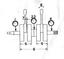
The beauty of this set up is that the left side of the motor is unchanged and the timing marks for the left cylinder and cam sprocket notch all still line up as per standard rebuild and cam set up, but now the right cylinder leads the left by 90°. once the camshaft has been rephased to give 270° firing interval and the ignition is modified to suit this experimental motor will become a reality! Update 2006 Several years have now passed since I wrote this original page and there are now quite a few rephased motors running around the world and to my delight the owners all report that the rephase is a resounding success. They all report that the reduction in vibration is significant and the bikes fitted with them have been transformed and are a pleasure to ride. One owner even suggested that Yamaha should recall all XS650's and rephase them then send them back to their owners with an apology for not rephasing them when they were new. To those who believed in this experiment and bought shafts and built rephased engines, thanks guys, you made all the work and time invested worth it. You are all members of a very exclusive club. Enjoy! There are a few things that need to be considered when assembling the rephased crank. The cam chain sprocket is a bit tricky as it is an interference fit to the new splined shaft and also has to engage with the notch in the left flywheel, this requires the need for a special tool according to the manual and can be purchased from a Yamaha dealer. That may have been true twenty years ago but I doubt the tool is available now! So how can we do it? Ok, I have been told it is quite simple to do using the following method, first fit the 1mm spacer, main bearing and circlip to the left (unmodified) flywheel. Don't forget to put some locktite 680 on the splines now press to splined shaft into flywheel assembly until it bottoms out. Now heat the sprocket and drop it onto the splined shaft making sure the tongue on the sprocket engages with the notch in the flywheel. Next assemble the right (modified) flywheel, with the 1mm spacer and main bearing. Locktite the splines and then press the assembly onto the splined shaft until the bearing meets the cam chain sprocket making sure you have 90° between the crank pins as shown in the picture above. The measurement between the inside machined faces of the flywheels should be 54mm. Make sure the right cylinder leads the left. You now have the centre section of your 90° crankshaft finished! The rest is simple, just follow the manual. Crankshaft Tolerances
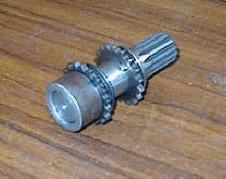
A tool I made to align
the cam sprocket boss to the #2 flywheel
notch. Without the special tool I am told it can be done by eye and some heat to allow the cam sprocket to drop onto the shaft after it is pressed into the flywheel. Remember the bearing, spacer and circlip must go in first and locktite 680 must be used on the splines.
My crank awaiting assembly Disclaimer These are experimental parts and as such no warranty is given or implied and if you decide to buy it is on the understanding that you do so at your own risk.
Sunday, 20 August 2017 |