 |
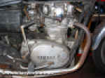
1. This looks like a challenge. We've decided to strip the engine completely and see what we find, though after standing for so long I anticipate spending some time with seized bolts and sheared off studs. The fuel tank and side panels come away easily, and I'm surprised to find the exhaust unbolts from the cylinder head without problems. Yamaha used big 10mm studs and dome nuts for the exhaust headers, so even after years of corrosion a good heave on a spanner slackens them off without shearing. So far so good. At this point I remove the sump drain screws and let the engine oil drain as work continues. |
| |
|
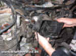 |
2. Removing the carbs on these bikes can be quite tricky as there is very little room between the rear of the cylinder head and the frame. I started by removing the air filters to make as much space as possible. |
| |
|
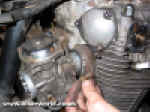 |
3. Even with the filters removed there's insufficient space to pull the carbs off, and I found it easiest to unbolt one of the inlet rubbers first. The carbs can then be waggled clear as an assembly, leaving one inlet rubber on the head. I unhooked the throttle and choke cables, then laid the carbs aside for attention later. The heavy smell of stale fuel confirms that the carbs will have to be completely stripped and rebuilt before we can even think of starting the engine later on. |
| |
|
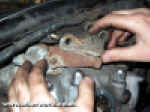 |
4. Next, the upper engine mountings. The head steady brackets themselves are quite heavily rusted but with a little persuasion all the bolts eventually come free without shearing. All bikes will suffer from some cosmetic corrosion in this area under the tank, as condensation accumulates here when the engine is warming up. |
| |
|
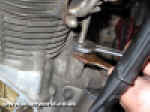 |
5. At the front of the engine this large diameter oil feed pipe runs upwards from the crankcase and branches into two seperate feeds for the rocker gear. A gland nut secures the pipe onto an adaptor screwed into the crankcase, and first attempts at unscrewing the pipe resulted in the adaptor loosening off with the gland nut securely rusted to it. Eventually I managed to use two 22mm open ended spanners to free it off, but it's easy to damage the pipe in the process. |
| |
|
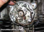 |
6. I continued the strip by removing the ignition components from each side of the head. The XS650 design is unique in that it carries the points on one side of the engine and the auto advance unit on the other, a shaft running through the centre of the hollow camshaft to link the two together. I marked the points
backplate with a screwdriver before removal so I can replace it in the same position later on. |
| |
|
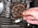 |
7. On the other side of the head the auto advance unit needs to be carefully dismantled for removal from the crossover shaft. A large flat sleeve nut holds the auto advance
backplate in place, once unscrewed the crossover shaft can be slid out of the camshaft and stored away. This whole mechanism may look complex at first glance but it's actually quite straightforward to work on, albeit a bit fiddly. |


![]()